UART TX with AXI-Stream interface (Verilog)
Most FPGA UARTs bolt on an ad-hoc “write strobe + busy” handshake. Giving the transmitter
a proper AXI4-Stream slave port instead means it plugs straight into a stream FIFO, a
DMA engine or any other AXIS source — tvalid/tready do the flow control for you, one
byte per beat. This is a standard 8N1 frame (start, 8 data LSB-first, stop) — the
self-checking testbench at the bottom passes 8/8 bytes in Icarus Verilog.
module uart_tx_axis #(
  parameter integer CLK_HZ = 50_000_000,
  parameter integer BAUD   = 115200
)(
  input  wire       clk,
  input  wire       rst_n,

  // AXI4-Stream slave — one byte per beat
  input  wire [7:0] s_tdata,
  input  wire       s_tvalid,
  output wire       s_tready,

  output reg        txd            // serial line, idles high
);
  localparam integer DIV = CLK_HZ / BAUD;

  reg [9:0] frame;                 // {stop, data[7:0], start}
  reg [3:0] idx;                   // bit index 0..9
  reg [$clog2(DIV) - 1 : 0] tick;  // baud-period counter
  reg       busy;

  assign s_tready = ~busy;         // accept a byte only when idle

  always @(posedge clk or negedge rst_n)
    if (!rst_n) begin
      txd  <= 1'b1;
      busy <= 1'b0;
      tick <= 0;
      idx  <= 0;
    end
    else if (!busy) begin
      txd <= 1'b1;
      if (s_tvalid) begin          // handshake: latch and start
        frame <= {1'b1, s_tdata, 1'b0};
        txd   <= 1'b0;             // start bit onto the line now
        idx   <= 0;
        tick  <= DIV - 1;
        busy  <= 1'b1;
      end
    end
    else if (tick != 0)
      tick <= tick - 1'b1;
    else begin                     // one baud period elapsed
      tick <= DIV - 1;
      if (idx == 9) begin
        busy <= 1'b0;             // stop bit done
        txd  <= 1'b1;
      end
      else begin
        idx <= idx + 1'b1;
        txd <= frame[idx + 1];    // next bit out
      end
    end
endmodule
How the handshake works
s_tready is high whenever the transmitter is idle. A transfer happens on the one clock
where both s_tvalid and s_tready are high — that cycle the byte is latched, the
start bit drops onto the line, and s_tready goes low until the full frame (10 bit
periods) has shifted out. The upstream source just holds tdata/tvalid until it sees
tready; no custom busy polling.
Testbench (self-checking)
Drive a handful of bytes over the stream and let an independent UART receiver model sample
the line and compare. Build and run with iverilog -g2012 -o sim design.v tb.v && vvp sim.
`timescale 1ns/1ps
module tb;
  localparam integer CLK_HZ = 1_000_000;
  localparam integer BAUD   = 100_000;        // DIV = 10
  localparam integer DIVN   = CLK_HZ / BAUD;
  localparam integer CLKP   = 10;             // ns clock period
  localparam integer BITNS  = DIVN * CLKP;    // ns per bit

  reg        clk = 0, rst_n = 0;
  reg  [7:0] s_tdata = 0;
  reg        s_tvalid = 0;
  wire       s_tready, txd;

  uart_tx_axis #(.CLK_HZ(CLK_HZ), .BAUD(BAUD)) dut (
    .clk(clk), .rst_n(rst_n),
    .s_tdata(s_tdata), .s_tvalid(s_tvalid), .s_tready(s_tready),
    .txd(txd)
  );

  always #(CLKP / 2) clk = ~clk;

  integer pass = 0, fail = 0;
  reg [7:0] expq [0:63];
  integer wptr = 0, rptr = 0;

  // AXI-Stream master: hold tdata/tvalid until accepted
  task send (input [7:0] b);
    begin
      @(posedge clk);
      s_tdata  <= b;
      s_tvalid <= 1'b1;
      @(posedge clk);
      while (s_tready !== 1'b1) @(posedge clk);
      s_tvalid <= 1'b0;
      expq[wptr] = b; wptr = wptr + 1;
    end
  endtask

  // UART receiver model: sample txd and check against the queue
  reg [7:0] got;
  integer k;
  initial begin
    wait (rst_n);
    forever begin
      @(negedge txd);                 // start bit
      #(BITNS / 2);                   // move to bit centre
      for (k = 0; k < 8; k = k + 1) begin
        #(BITNS);
        got[k] = txd;                 // LSB first
      end
      #(BITNS);                       // stop bit
      if (got === expq[rptr])
        $display("  PASS  sent=0x%02h  recv=0x%02h", expq[rptr], got);
      else begin
        $display("  FAIL  sent=0x%02h  recv=0x%02h", expq[rptr], got);
        fail = fail + 1;
      end
      pass = pass + (got === expq[rptr]);
      rptr = rptr + 1;
    end
  end

  initial begin
    repeat (4) @(posedge clk);
    rst_n = 1;
    repeat (2) @(posedge clk);
    send(8'h00); send(8'hFF); send(8'h55); send(8'hA5);
    send(8'h42); send(8'h01); send(8'h80); send(8'h3C);
    #(BITNS * 12);
    $display("  ==== %0d passed, %0d failed ====", pass, fail);
    $finish;
  end
endmodule
PASS sent=0x00 recv=0x00
PASS sent=0xff recv=0xff
PASS sent=0x55 recv=0x55
PASS sent=0xa5 recv=0xa5
PASS sent=0x42 recv=0x42
PASS sent=0x01 recv=0x01
PASS sent=0x80 recv=0x80
PASS sent=0x3c recv=0x3c
==== 8 passed, 0 failed ==== The
The txd line for 0xA5, captured from the simulation — start (0), eight data bits LSB-first, stop (1).
Run the same dump (uart_tx.vcd) in a waveform viewer to see it for real — here it is in GTKWave, the whole run and a zoom on one region:
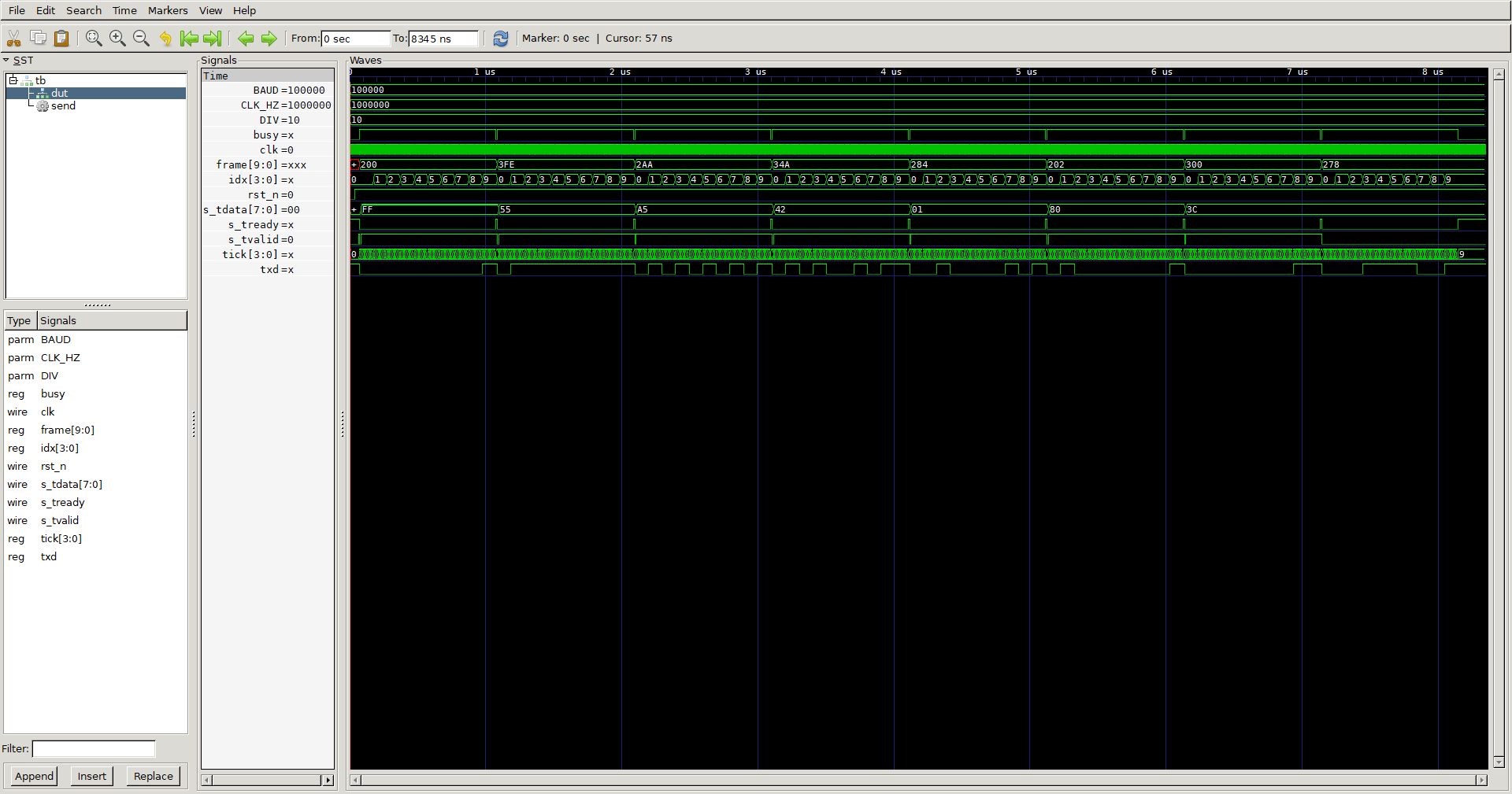 GTKWave — the full run: all eight bytes shift out as
 s_tdata cycles through them.
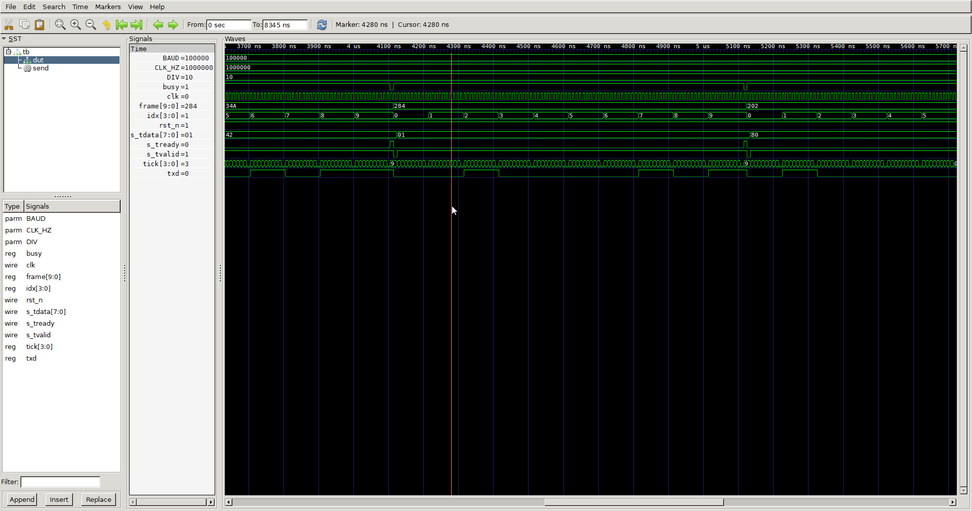 Zoomed in: the AXI-Stream handshake (
s_tvalid & s_tready high together for one clock), the idx bit counter running 0 → 9, and txd shifting the frame out — one bit every DIV clocks.
Usage
- Set
CLK_HZandBAUD;DIV = CLK_HZ / BAUDsets the bit period (use a fractional divider if your clock doesn’t divide evenly and you need tight baud accuracy — check the error with the UART baud calculator). - Feed it from an async FIFO when crossing clock domains (see the metastability & CDC notes).
- The RX side is the mirror image: a serial sampler driving an AXI-Stream master port
(
m_tdata/m_tvalid/m_tready).